
CFRP Power Dividers
Power dividers with a metallised carbon-fibre body for lightweight RF feed networks.


Cover fasteners
Hold the cover down on the body.
CFRP cover
Closes the channel network.
Metallised channels
The RF path: one input branching to four outputs.
Input port
Where the signal enters.
Output ports
Four equal outputs to the feed network.
CFRP body
Sets the geometry and stiffness of the divider.
CFRP power divider.
It splits an RF signal across several outputs, in a carbon-fibre body that takes mass out of the feed network.
Illustrative model, not to scale.
Taken apart. Scroll on to pull the connectors, lift the cover and see the channel network inside.
For lighter feed networks. For antenna feed networks, array antennas and satellite payload RF chains.
- Cover fasteners: Hold the cover down on the body.
- CFRP cover: Closes the channel network.
- Metallised channels: The RF path: one input branching to four outputs.
- Input port: Where the signal enters.
- Output ports: Four equal outputs to the feed network.
- CFRP body: Sets the geometry and stiffness of the divider.
What it is
A power divider splits an RF signal across several outputs. Building the body in CFRP lowers the mass of feed networks for space and airborne antennas.
RF surfaces are metallised to carry the signal; the composite body sets the geometry and stiffness.
Where it is used
- Antenna feed networks
- Array antennas
- Satellite payload RF chains
Goes with
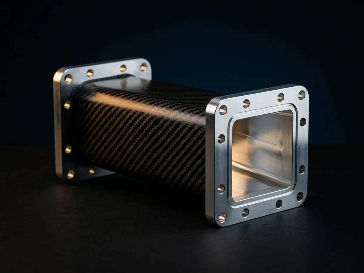
CFRP Metallised Waveguide
Waveguide in carbon fibre with a metallised internal surface.
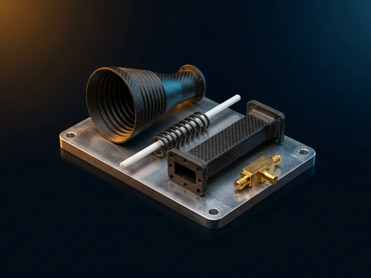
Satellite Antenna Sub-Systems
Satellite antenna sub-systems in CFRP/GFRP: corrugated horn, helical antenna, waveguide, mast adapter plates and bias tee.
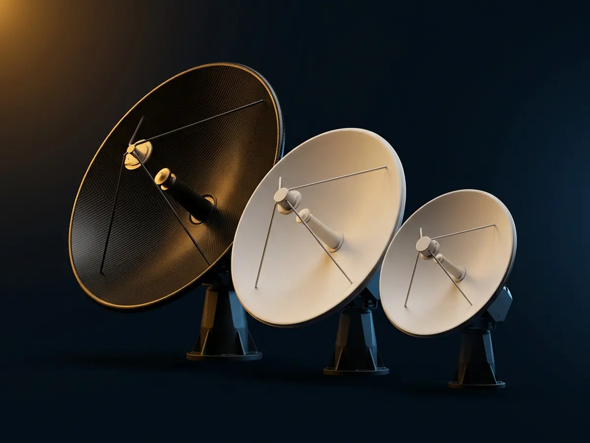
C, Ku and Ka Band Antennas
Antennas for satellite communication in C, Ku and Ka bands.


Request a quote.
Send the drawing or the requirement for CFRP Power Dividers, and an engineer will reply to scope the work.